Manage VPCs
Virtual Private Clouds (VPCs) in WiLine Edge Cloud (WEC) provide secure, isolated networking environments for your cloud resources. Use VPCs to define custom network topologies, subnets, IP ranges, and security policies.
The VPCs dashboard provides both a high-level summary and a detailed table of your Virtual Private Clouds.
At the top, you’ll see key statistics:
- Total VPCs — total number of VPCs across all zones
- Active VPCs — percentage of VPCs currently enabled
- Total Networks — total number of networks (subnets) across all VPCs
These metrics give you a quick overview of your network footprint and health.
VPCs Configuration
The form includes the following sections:
Open the VPCs page
After logging in to the WiLine Edge Cloud:
- Navigate to Networks → VPCs.
You will see a dashboard with statics and a table with a list of VPCs:
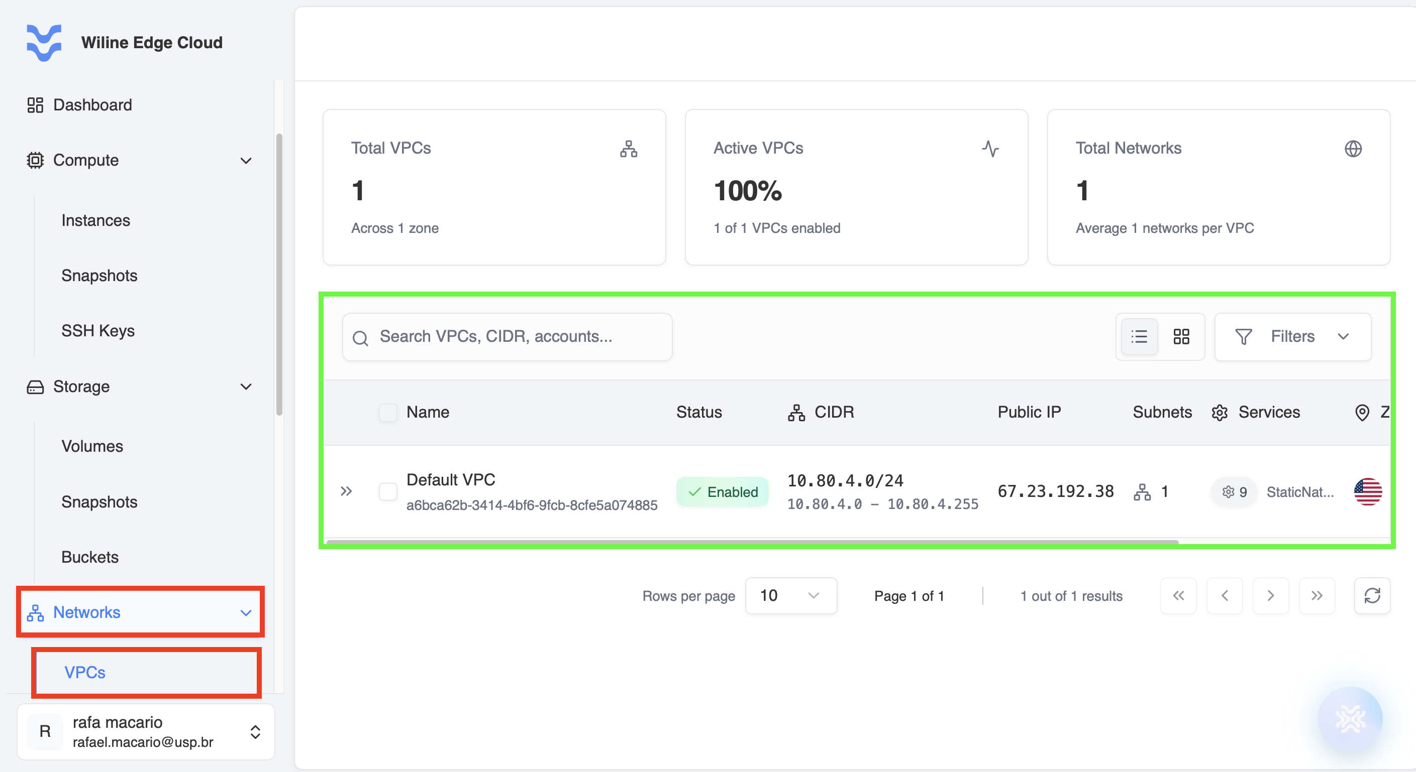
Figure 1: VPCs dashboard displaying all Virtual Private Clouds, their status, and key metrics.
Below the statistics, you’ll find a table listing all VPCs.
Each row represents a VPC and includes:
- Name & ID — unique identifiers
- Status — whether the VPC is enabled
- CIDR — IP range assigned to the VPC
- Public IP Range — available external IP range
- Subnets / Services — number of resources inside the VPC
- Zone — deployment location
- Created — creation timestamp
Actions column
Under the Actions column, clicking the icon reveals additional management options for each VPC:

Figure 2: Actions menu for managing a VPC.
The available actions include:
- View Details — opens the VPC management page where you can configure and monitor the VPC
Additional actions may be available depending on your environment and VPC state:
- Add Network — create and attach a new subnet to the VPC
- Acquire Public IP — allocate a public IP range for external connectivity
- Edit VPC — modify VPC configuration settings
- Configure — access advanced configuration options
- Delete VPC — permanently remove the VPC
Available actions may be enabled or disabled depending on the current state of the VPC and existing dependencies (e.g., attached subnets or running instances).
Selecting View Details opens a dedicated management page, similar to Virtual Machines and Volumes.
Manage Your VPC
To manage a VPC:
- Locate the VPC in the table (see Open the VPCs page)
- Click the from the Actions column
- Select View Details
:::info Control Panel
At the top of the management page, you’ll find a control panel with quick actions to manage your VPC.
These actions allow you to perform common operations without navigating between tabs:
- Refresh VPC Data — updates the VPC status and latest information
- Restart VPC — restarts VPC services (if applicable)
- Add Subnet — create a new subnet within the VPC
- Acquire Public IP — allocate public IP addresses for external access
- Delete VPC — permanently remove the VPC
Some actions may be enabled or disabled depending on the current state of the VPC and whether it has active resources (such as subnets or instances). :::
After selecting a VPC, a management page provides detailed options organized into the following tabs:
Overview
- View and copy general VPC information such as name, ID, and status
- See network configuration:
- CIDR Block — defines the IP range of the VPC
- Available Range — usable IP addresses within the CIDR
- Total Addresses — total number of IPs in the network
- Review router configuration (e.g., redundant or distributed routing)
- Manage tags for organization and filtering
This tab provides a high-level summary of the VPC configuration and network structure:
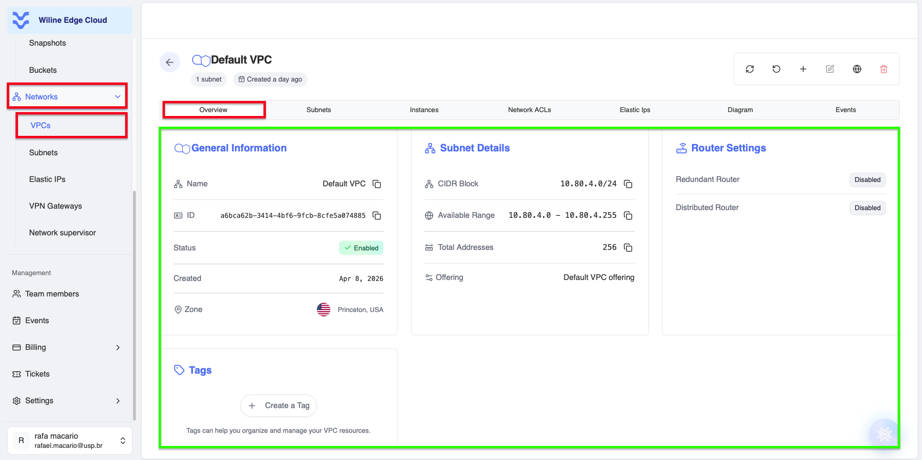
Figure 3: Overview tab showing general VPC information and network configuration.
Example: VPC Overview
General Information
- Name:
Default VPC - ID:
a6bca62b-3414-4bf6-9fcb-8cfe5a074885 - Status:
Enabled - Created:
Apr 8, 2026 - Zone:
Princeton, USA
Subnet Details
- CIDR Block:
10.80.4.0/24 - Available Range:
10.80.4.0 - 10.80.4.255 - Total Addresses:
256 - Offering:
Default VPC offering
Router Settings
- Redundant Router:
Disabled - Distributed Router:
Disabled
This example represents a standard VPC with a single subnet and a full /24 private IP range.
Subnets
- View all subnets within the VPC
- Understand how the network is segmented
- Delete subnets if needed
Subnets define smaller network segments inside your VPC:
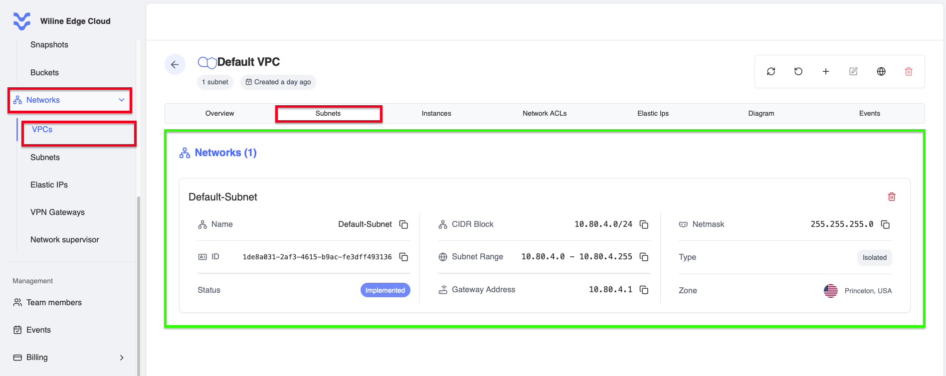
Figure 4: Subnets tab displaying all subnets within the VPC.
Example: a VPC Subnet
- Name:
Default-Subnet - ID:
1de8a031-2af3-4615-b9ac-fe3dff493136 - Status:
Implemented - CIDR Block:
10.80.4.0/24 - Subnet Range:
10.80.4.0 - 10.80.4.255 - Gateway Address:
10.80.4.1 - Netmask:
255.255.255.0 - Type:
Isolated - Zone:
Princeton, USA
This subnet spans the full VPC range and is configured as an isolated network.
Instances
- View all virtual machines connected to this VPC
- Understand which resources are using the network
- Manage and monitor virtual machines connected to the VPC
VPC instances are virtual machines running inside a VPC, using its network and rules:
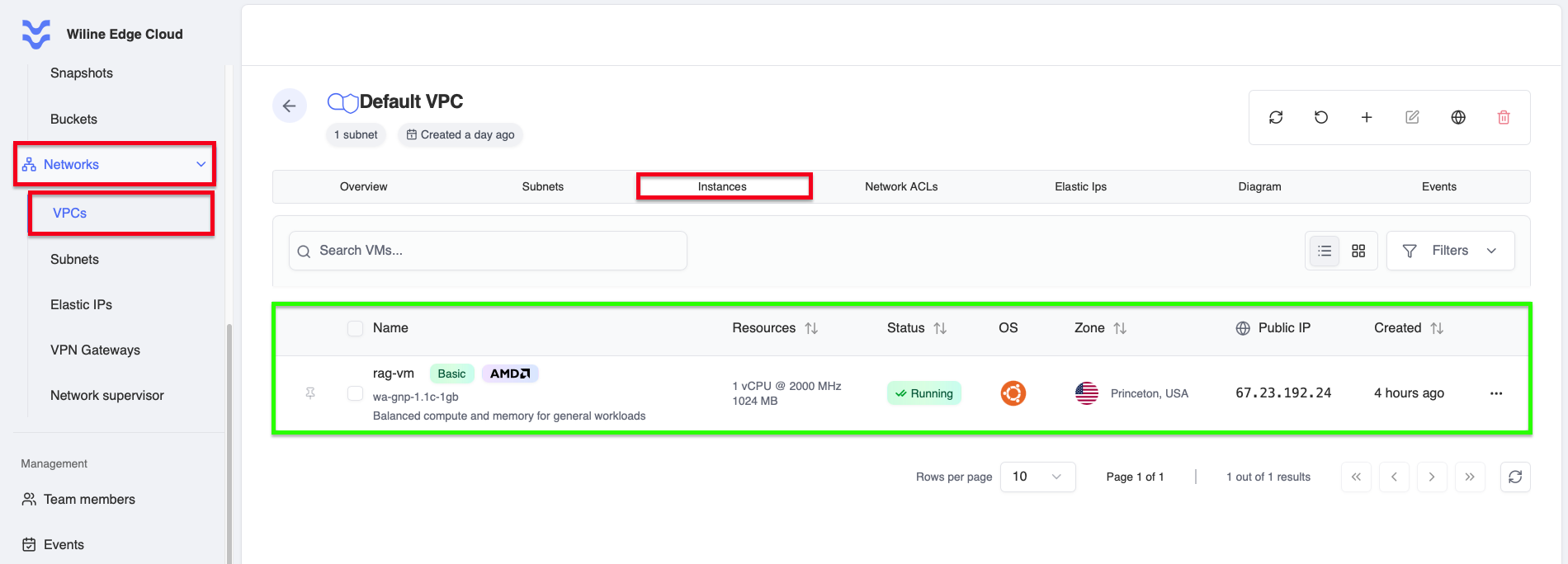
Figure 5: Instances tab showing virtual machines connected to the VPC.
Example: a VPC Instance
- Name:
rag-vm - Service Offering:
wa-gnp-1.1c-1gb - CPU:
1 vCPU @ 2000 MHz - Memory:
1024 MB - Status:
Running - OS:
Ubuntu 24.04 LTS - Zone:
Princeton, USA - Public IP:
67.23.192.24 - Created:
4 hours ago
This example shows a running virtual machine connected to the VPC with an allocated public IP.
Network ACLs
Network ACLs (Access Control Lists) allow you to control traffic at the subnet level by defining rules that either allow or deny network traffic.
When you open this tab, you will typically see two default ACLs:
- default_allow — allows all traffic
- default_deny — blocks all traffic
Each ACL represents a set of rules applied to traffic entering or leaving subnets.
Figure 6: Network ACLs tab displaying ACLs and their associated rules.
ACL Structure
Each ACL can be expanded to reveal two types of rules:
- Ingress Rules — control incoming traffic
- Egress Rules — control outgoing traffic
Each rule contains:
- Direction — Ingress or Egress
- Protocol — e.g.
ALL,TCP,UDP - Ports — specific ports or ranges (e.g.
80,443,All) - CIDR Block — IP range (e.g.
0.0.0.0/0for all traffic) - Action —
AlloworDeny - State — rule status (e.g. Active)
Example:
Ingress | ALL | All | 0.0.0.0/0 | Allow→ allows all incoming trafficEgress | ALL | All | 0.0.0.0/0 | Deny→ blocks all outgoing traffic
ACL Actions
Each ACL has an Actions menu () with the following options:
- Add New Rule — create a new ACL rule
- Edit ACL — update the ACL name or description
- Delete ACL — remove the ACL
Rule Actions
Each individual rule also has its own Actions menu, where you can:
- Edit Rule — modify protocol, ports, or CIDR
- Delete Rule — remove the rule permanently
Creating a Rule
When you click Add New Rule, you will configure:
- Protocol — type of traffic (e.g. TCP, UDP, ALL)
- Action — Allow or Deny
- Direction — Ingress (incoming) or Egress (outgoing)
- CIDR Block — IP range in CIDR notation (e.g.
192.168.1.0/24) - Ports — specific ports or ranges
- Priority (Position) — order in which rules are evaluated
- Description (optional) — explanation for the rule
ACL rules are evaluated based on their priority, so ordering is important.
Use Allow rules to explicitly permit required traffic (e.g., HTTP/HTTPS), and Deny rules to block unwanted access.
A common pattern is:
- Allow specific traffic (e.g. port 22 for SSH)
- Deny everything else for stricter security
Key Concept
- default_allow → open network (less secure, useful for testing)
- default_deny → restrictive network (more secure, recommended for production)
Network ACLs provide an additional layer of security, complementing firewalls and security groups.
Elastic IP
This tab displays a table of all public (Elastic) IP addresses associated with the VPC.
Each row represents an IP and includes:
- IP Address — the public IP
- Status — e.g.
Allocatedor unassigned - Instance — VM currently using the IP (if any)
- Network — associated subnet
- Zone — deployment location
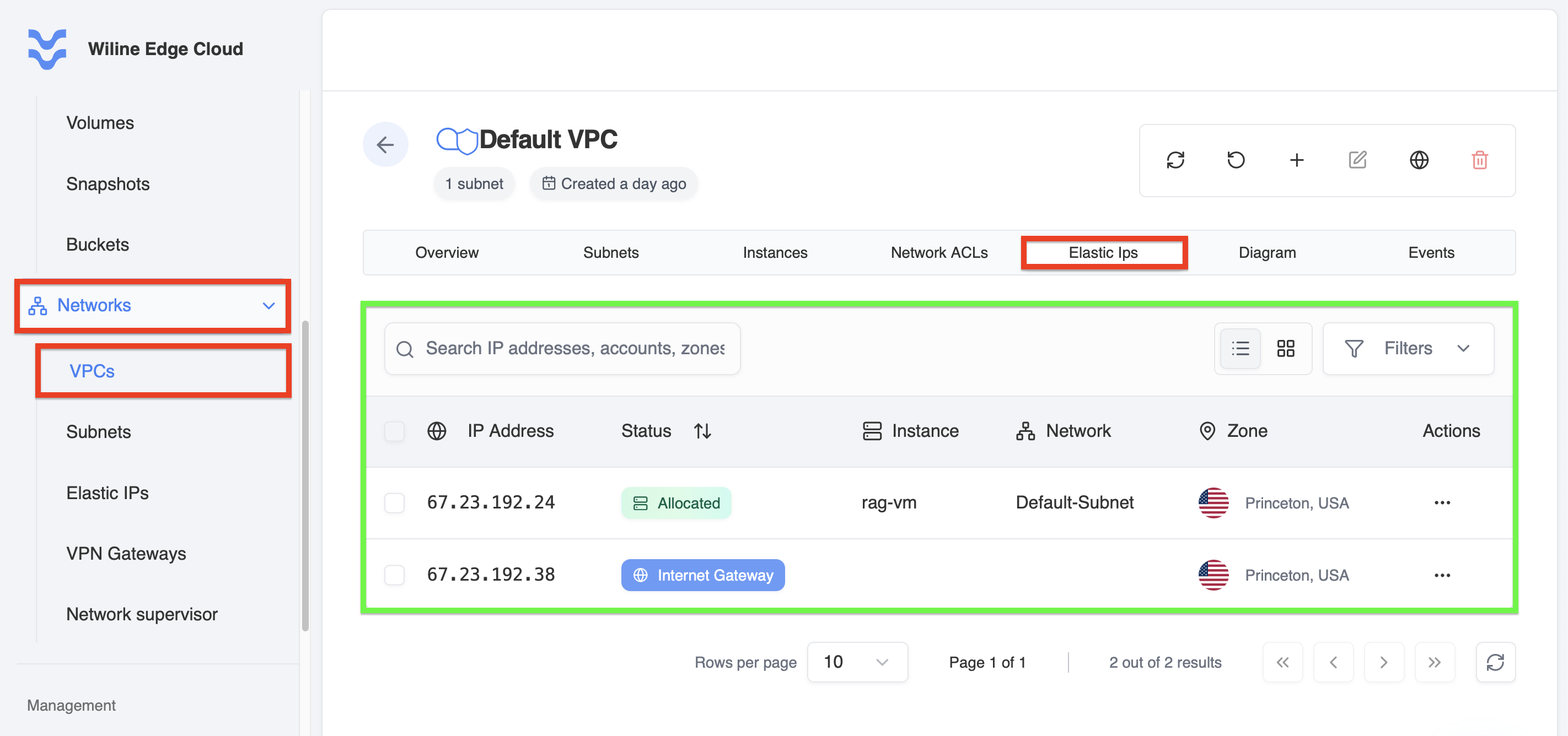
Figure 7: Elastic IPs tab showing public IPs and their allocation status.
What this means
- Allocated → the IP is currently attached to a VM
- No instance → the IP is available but not in use
This table helps you understand which resources are publicly accessible and manage external connectivity.
Actions (per IP)
In the Actions column (), you can manage each IP individually.
Available actions depend on whether the IP is already allocated:
If the IP is NOT allocated
- Allocate to VM — attach the IP to a virtual machine
- View Details — view IP configuration
If the IP IS allocated
- Allocate to VM — reassign to another VM (if supported)
- View Details — see mapping and configuration
- Detach IP from VM — remove the IP from the current VM (disables Static NAT)
- Release IP — permanently release the IP back to the pool
Available actions are enabled or disabled depending on whether the IP is currently attached to a VM.
Allocate IP to a VM
When you click Allocate to VM, you will:
- Select a virtual machine within the same VPC
- Confirm the allocation
- Click Allocate IP
What happens:
- The public IP is mapped directly to the VM
- This enables external access via Static NAT
Detach IP from VM
When you select Detach IP from VM:
- You will be prompted to disable Static NAT
- This removes the public IP from the VM
Result:
- The VM is no longer accessible via that public IP
- The IP returns to an unallocated state
Release Public IP
When you click Release IP:
- You will see a confirmation dialog
- Confirm by clicking Release IP
This action cannot be undone. The IP will be returned to the public pool and may not be recoverable.
View Details
The View Details option displays:
- Current allocation (which VM is using the IP)
- Network and zone information
- Status and configuration
Use this to audit connectivity and troubleshoot access issues.
Diagram
- Visualize relationships between VPC components
- Understand how subnets, instances, and IPs are connected
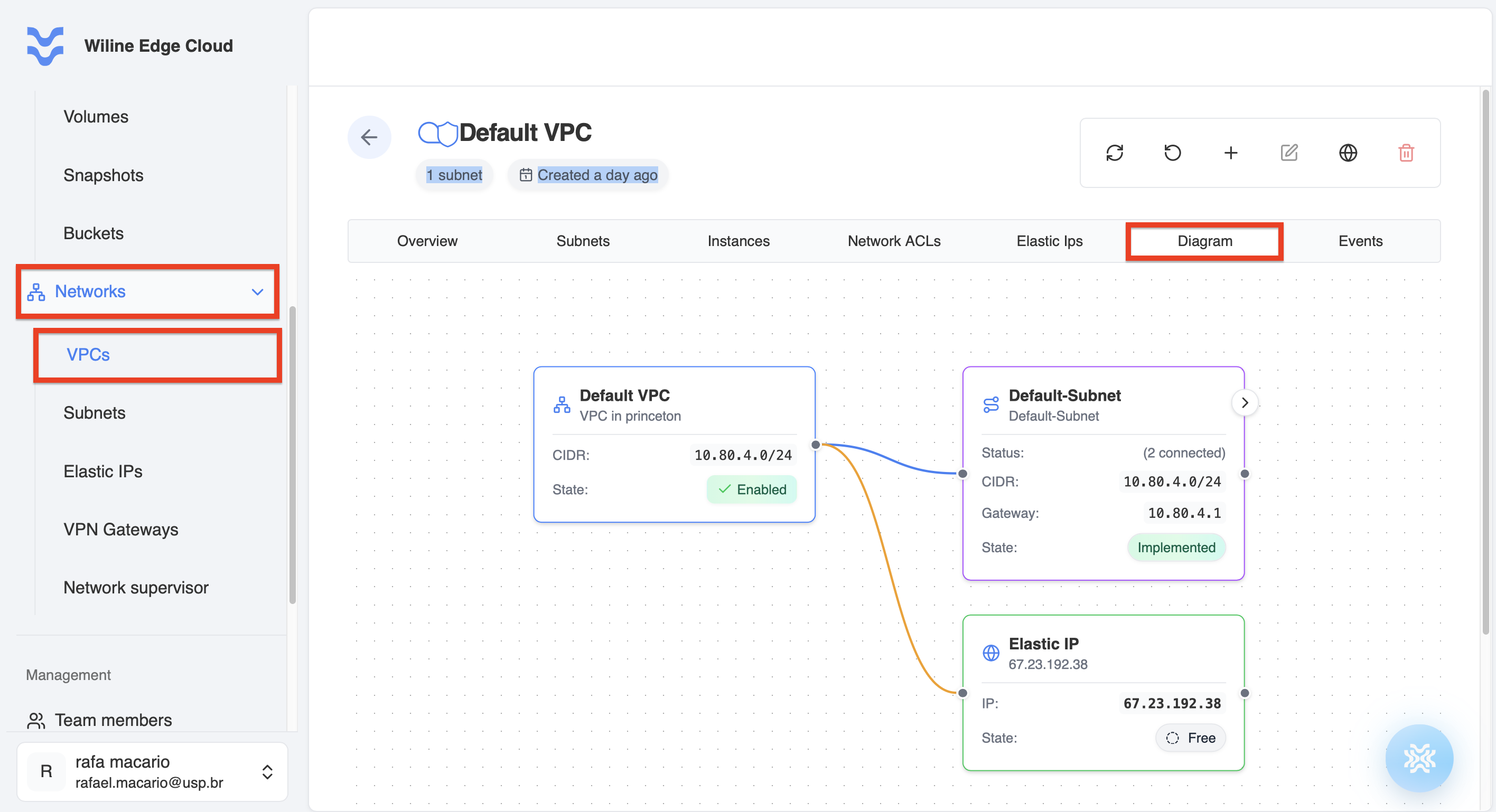
Figure 8: Diagram view illustrating relationships between VPC components.
Events
- Track all actions performed on the VPC
- Filter events for troubleshooting and auditing
Each event represents a system or user action (e.g., VPC creation or subnet updates).
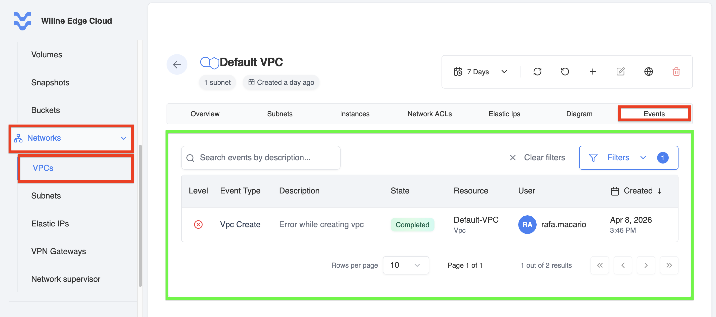
Figure 9: Events tab displaying activity logs and system actions for the VPC.
After Creation
Once your VPC is created and configured, you can continue managing and optimizing it.
- Review VPC details by clicking on a VPC name.
- Adjust security settings and firewall rules as needed.
- Ensure proper zonal placement for redundancy.
Next steps
- Create Subnets to segment your VPC.
- Attach services such as VMs or databases.
- Configure firewall rules to control access.